
I realize it’s been a long time since I posted, but I assure you I’m still working on this almost every free chance I get. It’s been rather slow going because I’m not really familiar with physics or loading meshes manually. I’ve been reading over the Jolt Physics docs and code to try to understand how everything kind of works.
Right now my major road block is loading the level into the server and having collision geometry generated for it. To complicate matters, Unreal uses a left handed coordinate system whereas Jolt uses a right handed coordinate system. To make sure everything works as expected I’d like to visualize the map after it’s loaded. To do that, I’m going to re-use the JoltPhysics samples applications which comes with a handy debug renderer.
I originally had planned on using the assimp library to load models, but I came to the conclusion that it was a bit heavy and I didn’t really like the API. Also it was kind of a pain to jam it into JoltPhysics’ cmake files as assimp fails a lot of the -Wall compile checks (and the project is set to treat warnings as errors, complicating the matter).
My engine only really needs to load FBX files for the landscapes (which will generate collision geometry), so I searched around until I came across the pretty great ufbx library.
The next step was getting the JoltPhysic’s build system to include the ufbx library.
Building ufbx into JoltPhysic’s Samples
The library states to build it, simply:
Copy
ufbx.handufbx.cto your project,ufbx.cneeds to be compiled as C99/C++11 or more recent. You can also addmisc/ufbx.natvisto get debug formatting for the types.
I don’t know if this is a product of MSVC, but I had to rename the ufbx.c file to ufbx.cpp to get it to work in the cmake build.
Here’s the changes I made to the Samples.cmake.
diff --git a/Samples/Samples.cmake b/Samples/Samples.cmake
index 4c072caf..cb68e7fc 100644
--- a/Samples/Samples.cmake
+++ b/Samples/Samples.cmake
@@ -278,6 +278,8 @@ set(SAMPLES_SRC_FILES
        ${SAMPLES_ROOT}/Utils/ShapeCreator.h
        ${SAMPLES_ROOT}/Utils/SoftBodyCreator.cpp
        ${SAMPLES_ROOT}/Utils/SoftBodyCreator.h
+       ${SAMPLES_ROOT}/ThirdParty/ufbx/ufbx.cpp
+       ${SAMPLES_ROOT}/ThirdParty/ufbx/ufbx.h
 )
With those changes in place, I re-ran the Build/cmake_vs2022_cl.bat file and regenerated my Visual Studio project files. I may have had to shut off fail on error build checks to get it to compile, but I forget. So if you get errors about it not being able to build, right click Samples and set Samples -> properties -> C/C++ -> General -> Level2 (/W2)
The Samples application is well designed so I ended up just choosing a random test case to modify to load my landscape into, BoxShapeTest.cpp.
How the hell do FBX files work, and how does Jolt expect the Mesh(s)?
This was my first major hurdle, that took a lot of trial and error. I always assumed I’d just have a list of vertices and I’d pass that into Jolt and it would build it out for me. Turns out no, you need more information than that.
Looking through the test cases, I realized I need to create a MeshShapeSettings object. It can take either a list of triangles, or a list of vertices and a list of indexed triangles. I finally figured out how to get the data from ufbx by iterating over the meshes then iterating over the Mesh->vertices and pushing onto an Array the vertex values.
JPH::VertexList VertList;
JPH::IndexedTriangleList TriList;
for (auto& Vertex : Mesh->vertices)
{
	// This is not correct, but it's what I started with
	VertList.push_back(JPH::Float3(Vertex.x, Vertex.y, Vertex.z));
}
I now need the Triangles. I used GitHub code search to figure out how to get the vertex_indices data. You basically iterate over the number of indices, adding 3 each time and doing something like:
for (size_t i = 0; i < Mesh->num_indices; i+=3)
{
	auto idx0 = Mesh->vertex_indices[i];
	auto idx1 = Mesh->vertex_indices[i + 1];
	auto idx2 = Mesh->vertex_indices[i + 2];

	JPH::IndexedTriangle triangle(idx0, idx1, idx2);

	TriList.push_back(triangle);
}
I can now create my MeshShapeSettings!
MeshShapeSettings mesh_settings(std::move(VertList), std::move(TriList));
mesh_settings.SetEmbedded();
BodyCreationSettings floor_settings(&mesh_settings,RVec3(Vec3(0.0f, 0.0f, 0.0f)), Quat::sIdentity(), EMotionType::Static, Layers::NON_MOVING);
Body &floor = *mBodyInterface->CreateBody(floor_settings);
mBodyInterface->AddBody(floor.GetID(), EActivation::DontActivate);
I load up my test and am greeted with this:
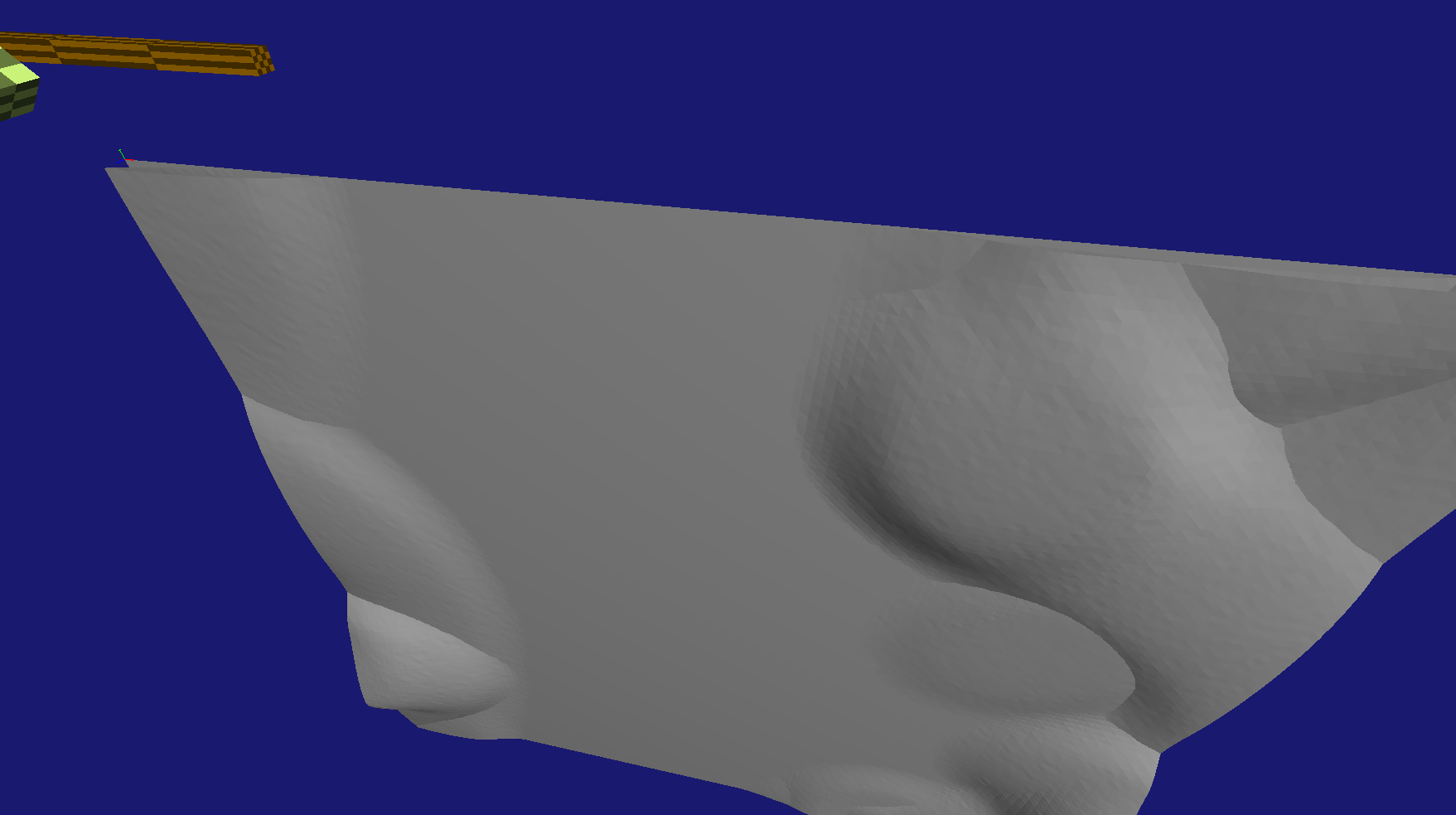
So… that’s weird. To confirm what it should look like I loaded my landscape that I exported from UE5 into Blender:
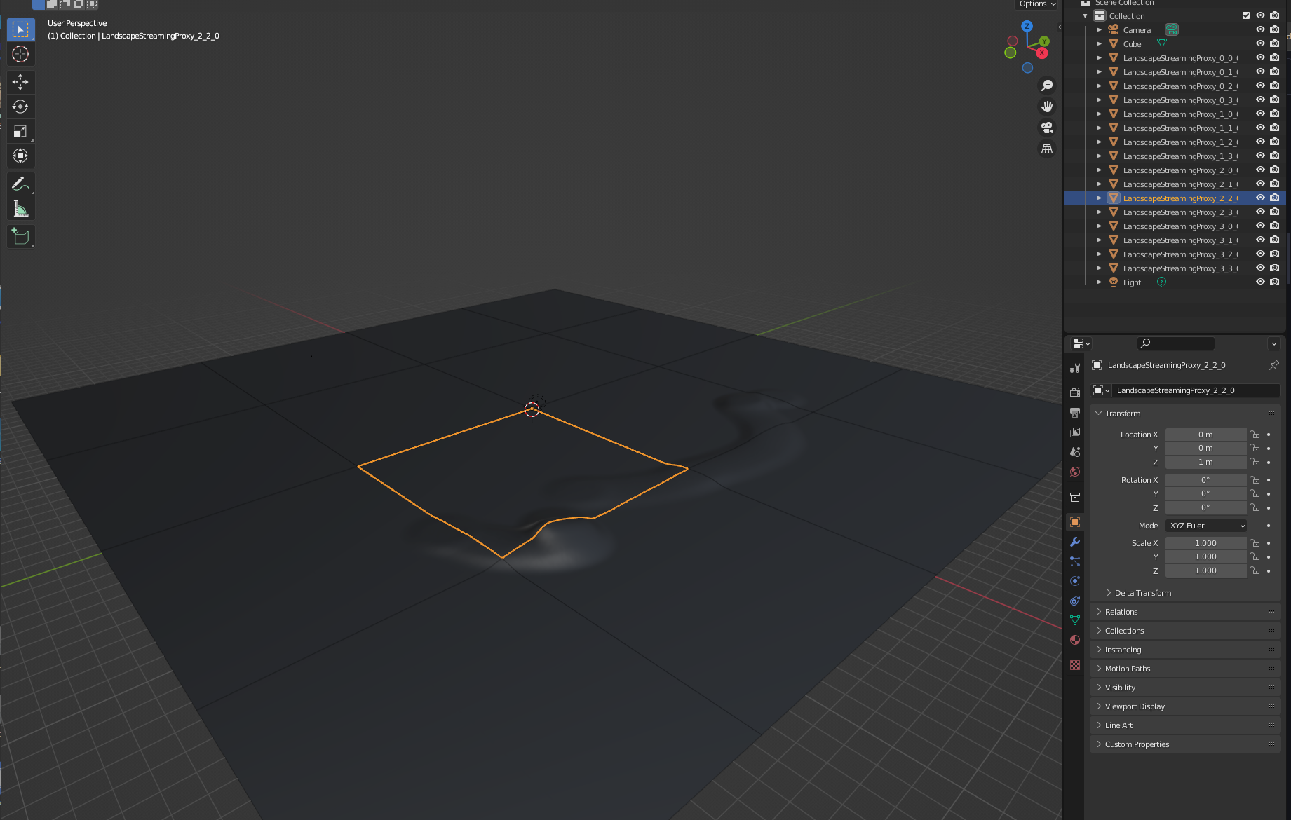
I didn’t realize, but when exporting the landscape from UE5 it breaks the mesh into the segments. When loading into Jolt, I’m just shoving all of the meshes at the origin (0.f, 0.f 0.f) and they are stacking on top of each other, i need to figure out how to get the world position so I can offset them correctly!
Position Trail and Error
I’ll admit I don’t really know much about meshes, so I was looking through the ufbx code and see just tons of ways to store transform data. I also searched through the ufbx issues post and found this hint from the author about using a transform_position function. I decided to debug it the old printf way (except to a log file) to figure out what values I should use.
std::string File = "D:\\Temp\\out.log";
auto Out = std::ofstream(File, std::ios::out | std::ios::trunc);
// open fbx etc...
for (auto& Vertex : Mesh->vertices)
{
	Out << "mesh id:\t" << Mesh->element_id;
	PrintVec3(Out, Vertex);
	Out << '\n';

	auto N2W = ufbx_transform_position(&node->node_to_world, Vertex);
	Out << "mesh id N2W: " << Mesh->element_id;
	PrintVec3(Out, N2W);
	Out << '\n';

	auto N2P = ufbx_transform_position(&node->node_to_parent, Vertex);
	Out << "mesh id N2P: " << Mesh->element_id;
	PrintVec3(Out, N2P);
	Out << '\n';

	auto G2N = ufbx_transform_position(&node->geometry_to_node, Vertex);
	Out << "mesh id G2N: " << Mesh->element_id;
	PrintVec3(Out, G2N);
	Out << '\n';

	auto G2W = ufbx_transform_position(&node->geometry_to_world, Vertex);
	Out << "mesh id G2W: " << Mesh->element_id;
	PrintVec3(Out, G2W);
	Out << '\n';

	auto T = node->local_transform.translation;
	auto Loc5 = ufbx_vec3{T.x + Vertex.x, T.y + Vertex.y, T.z + Vertex.z};
	Out << "mesh id LTT: " << Mesh->element_id;
	PrintVec3(Out, Loc5);
	Out << '\n';
    // and so on...
}
This gave me some output to look at:
mesh id:	 1	x: 0	y: -0	z: 0
mesh id N2W: 1	x: -25200	y: 25200	z: 100
mesh id N2P: 1	x: -25200	y: 25200	z: 100
mesh id G2N: 1	x: 0	y: 0	z: 0
mesh id G2W: 1	x: -25200	y: 25200	z: 100
mesh id LTT: 1	x: -25200	y: 25200	z: 100
...the rest of the meshes ...
mesh id:	 16	x: 126	y: -126	z: 0
mesh id N2W: 16	x: 25200	y: -25200	z: 100
mesh id N2P: 16	x: 25200	y: -25200	z: 100
mesh id G2N: 16	x: 126	y: -126	z: 0
mesh id G2W: 16	x: 25200	y: -25200	z: 100
mesh id LTT: 16	x: 12726	y: -12726	z: 100
I tried these values but it ended up placing my meshes in VERY far away places from the origin. Again, I looked to blender to show me what I should be getting:
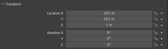
Those numbers look pretty close, except the scale is off, I just need to find the correct scale (yes, I know it’s 100, but I want to get the data from the FBX).
I finally found node->local_transform->scale and now we have the correct scale and position:
for (auto& Vertex : Mesh->vertices)
{
	auto N2W = ufbx_transform_position(&node->node_to_world, Vertex);
	auto LS = node->local_transform.scale;
	auto Scaled = JPH::Float3(N2W.x / LS.x, N2W.y / LS.y, N2W.z / LS.z);
	VertList.push_back(Scaled);
}
Loading up this latest change gets us…:
Nice! Except the rotation is off, unfortunately I didn’t see any rotation data in any of the attributes or fields of the FBX. I can only assume I’m loading it wrong or not processing correctly in it some way. (Maybe this is the left/right hand coordinate system problem??)
Regardless, to get things working I just rotated the meshes manually:
// Flip the X axis by -180 degrees
auto Rot = JPH::Quat::sRotation(Vec3::sAxisX(), -.5F * JPH_PI)
BodyCreationSettings floor_settings(&mesh_settings,RVec3(Vec3(0.0f, 0.0f, 0.0f)),  Rot, EMotionType::Static, Layers::NON_MOVING);
Body &floor = *mBodyInterface->CreateBody(floor_settings);
mBodyInterface->AddBody(floor.GetID(), EActivation::DontActivate);
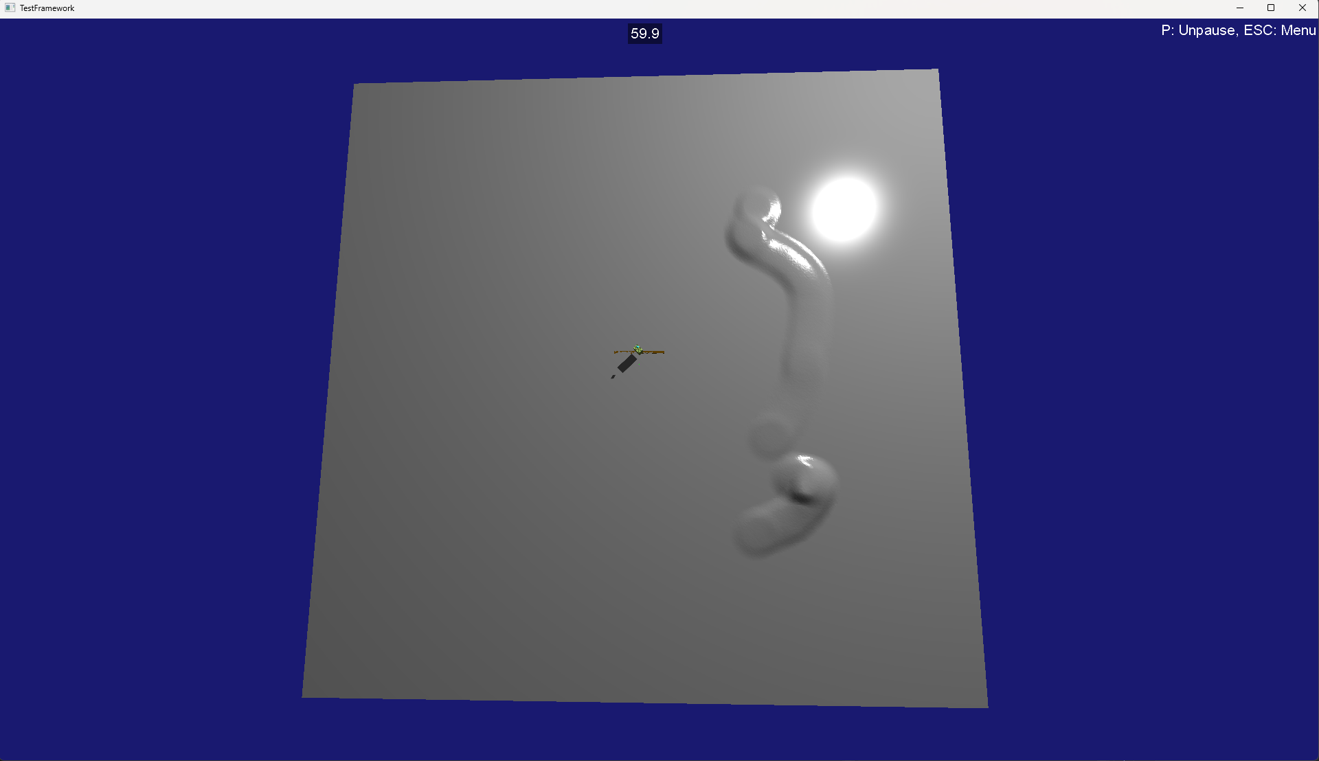
And viola:
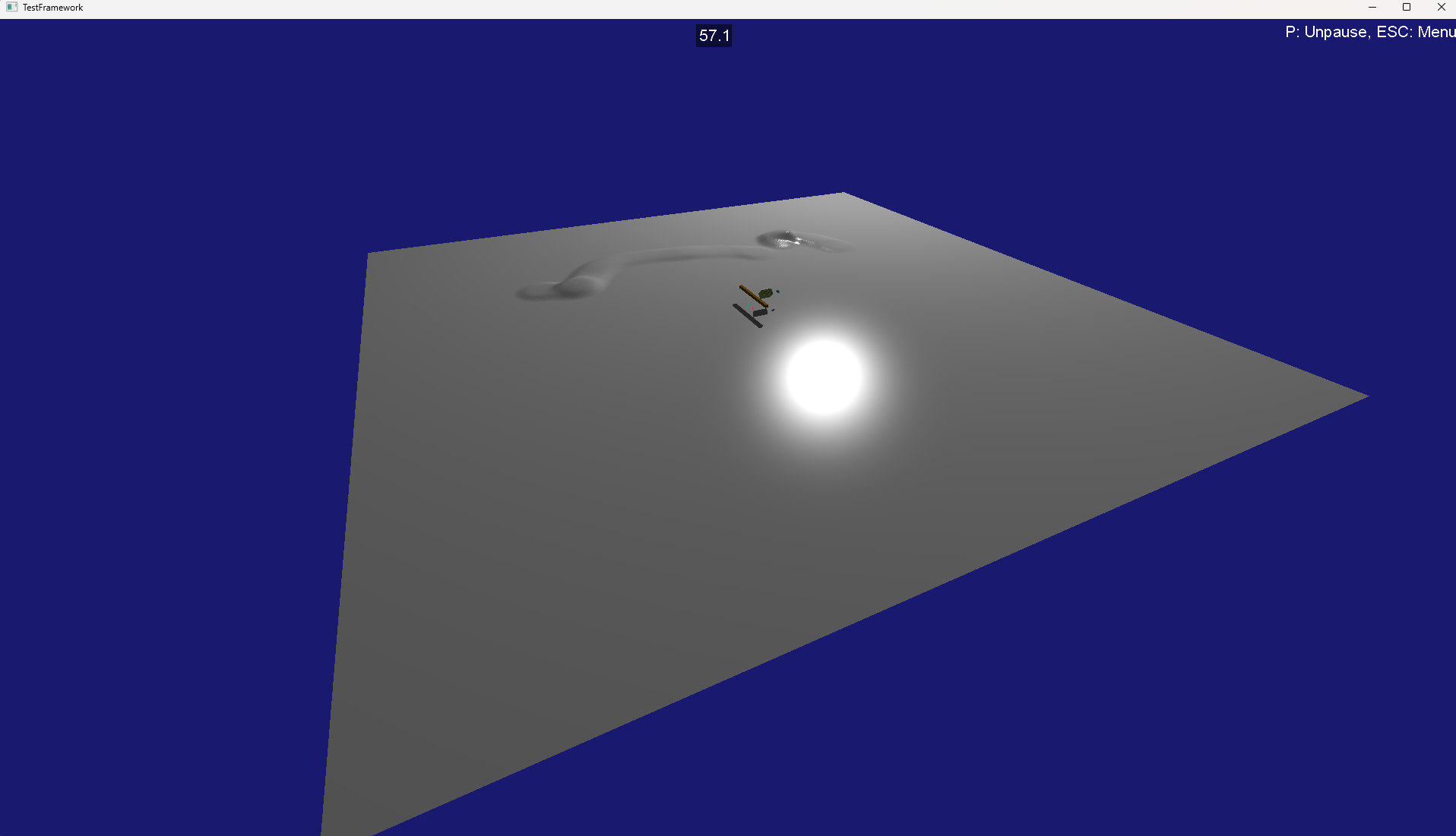
Our landscape is now loaded acts as a proper collision geometry, and just as it would look in UE5! If you want the full test file, I threw it up as a snippet.
Keep in mind you’d only do this loading once, and then save the serialized/optimized MeshShape data out. You could even make it a standalone binary to read FBX and then output serialized Jolt mesh binary files (which I may do!).
Now I need to get ufbx into my pmo server code and start seeing how to integrate jolt physics into flecs!
